初めてのPICプログラム
下記のプログラムは、LEDを0.5秒間隔で点滅するものである。
mainの中のループ以外はおまじないのようなもの。変更する必要はない。
RB0 = 1;
でLEDを点灯し、
__delay_ms(500);
で0.5秒待つ。そして、
RB0 = 0;
でLEDを消灯して、再度
__delay_ms(500);
で0.5秒待つ。
while(1)で無限ループにしているので、0.5秒間隔でLEDが点灯と点滅を繰り返す。
動作は以下のような動きになります。ソースコードは動画の後。
// PIC16F1827 Configuration Bit Settings

// 'C' source line config statements

#include <xc.h>

// #pragma config statements should precede project file includes.
// Use project enums instead of #define for ON and OFF.

// CONFIG1
#pragma config FOSC = INTOSC    // Oscillator Selection (INTOSC oscillator: I/O function on CLKIN pin)
#pragma config WDTE = ON        // Watchdog Timer Enable (WDT enabled)
#pragma config PWRTE = OFF      // Power-up Timer Enable (PWRT disabled)
#pragma config MCLRE = ON       // MCLR Pin Function Select (MCLR/VPP pin function is MCLR)
#pragma config CP = OFF         // Flash Program Memory Code Protection (Program memory code protection is disabled)
#pragma config CPD = OFF        // Data Memory Code Protection (Data memory code protection is disabled)
#pragma config BOREN = ON       // Brown-out Reset Enable (Brown-out Reset enabled)
#pragma config CLKOUTEN = OFF   // Clock Out Enable (CLKOUT function is disabled. I/O or oscillator function on the CLKOUT pin)
#pragma config IESO = ON        // Internal/External Switchover (Internal/External Switchover mode is enabled)
#pragma config FCMEN = ON       // Fail-Safe Clock Monitor Enable (Fail-Safe Clock Monitor is enabled)

// CONFIG2
#pragma config WRT = OFF        // Flash Memory Self-Write Protection (Write protection off)
#pragma config PLLEN = ON       // PLL Enable (4x PLL enabled)
#pragma config STVREN = ON      // Stack Overflow/Underflow Reset Enable (Stack Overflow or Underflow will cause a Reset)
#pragma config BORV = LO        // Brown-out Reset Voltage Selection (Brown-out Reset Voltage (Vbor), low trip point selected.)
#pragma config LVP = ON         // Low-Voltage Programming Enable (Low-voltage programming enabled)


#include <xc.h>
#define _XTAL_FREQ 8000000

void main(void){
    OSCCON = 0b01110010; // 内部クロック8MHz   4MHz 0b01101010
    ANSELA = 0b00000000; // アナログは使用しない。すべてデジタルI/Oに割り当てる
    ANSELB = 0b00000000; //

    TRISA = 0b00100000;  // RA5だけ入力。その他のピンは出力に割り当てる。(RA5は入力専用)
    TRISB = 0b00000000;  //

    PORTA = 0;  // 出力ピンの初期化(すべてLOWにする)
    PORTB = 0;

    while(1){
        RB0 = 1;
        __delay_ms(500);
        RB0 = 0;
        __delay_ms(500);
    }
}
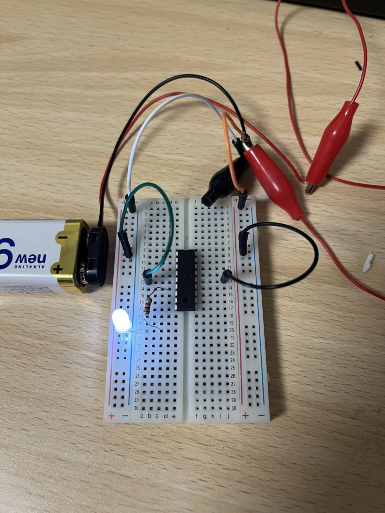
下の写真は、PIC Kit3でPICにプログラムを書き込み、ブレッドボードで動作させている状態。